ARM Processor Design Description
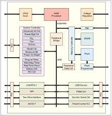
processor model is based on the ARM 720T instruction set. It features a 5-stage pipeline and is modeled in Figure 1 below. The beginning of the process starts in the program counter (PC). This increments by one each clock cycle unless there is a branch instruction. The output from the PC goes to the instruction memory which outputs a 32-bit instruction from the address location specified by the PC. The instruction is loaded into the FD Register which sets ‘Regwrite’ (bit that indicates whether the register file will be written to). It also sends the instruction to the DE Register and MUX which selects the arguments which will be used for logic functions. The DE Register sends instructions to the arithmetic logic unit (ALU) which performs all logic functions and branch instructions. After the logic function has been performed by the ALU, the result is passed to the EM Register. The EM Register holds the value to be passed onto RAM if the load or store signal is given. The MM Register then either gets values from the EM Register or the RAM and writes to the Register File.
The whole purpose of the pipeline is to execute one instruction per stage at a time. If there was no pipeline, the whole process would have to wait for one instruction to fully execute taking more time per instruction. This pipeline model is similar to an assembly line in which different processes can be completed at each stage of the pipeline.
ARM Processor Design
ARM Processor Design
ARM Processor Design
ARM Processor Design
ARM Processor Design
ARM Processor Design
ARM Processor Design
ARM Processor Design
ARM and IBM develop 14nm processor - YouTube
New ARM processor-based Industrual solutions
No comments:
Post a Comment